
Applications
1. Applied to API Plan 52 or 53 pressured system, which mainly includes buffer fluid reservoir, mechanical seal, monitoring part, control part and pipes
2.Main function is to control mechanical seal`s temperature, improve its lubrication condition and control its working pressure in order to prevent from pollution and provide alarm when seal leakage happens. It will build an ideal working environment for mechanical seal, improve reliability and safety of mechanical seal and prolong its life time.
Function:
1. The fluid reservoir can be used as seal support system of multi stage mechanical seal, but it must contain buffer fluid or barrier fluid. Heat transfer can be carried with self circulation (thermosyphon) or force circulation by adding pumping ring, inert gas can be selected as pressure source.
2. Cooling effect depends on cooling pipe, when the pipe is installed correctly, thermosyphon (self circulation) should be produced automatically. Cooling effect can be improved through proper circulation device (such as mechanical seal`s pumping)
3. The effect will be realized only the reservoir works with other accessories together.
1. HR Series Fluid Reservoir
Operating limits and descriptions
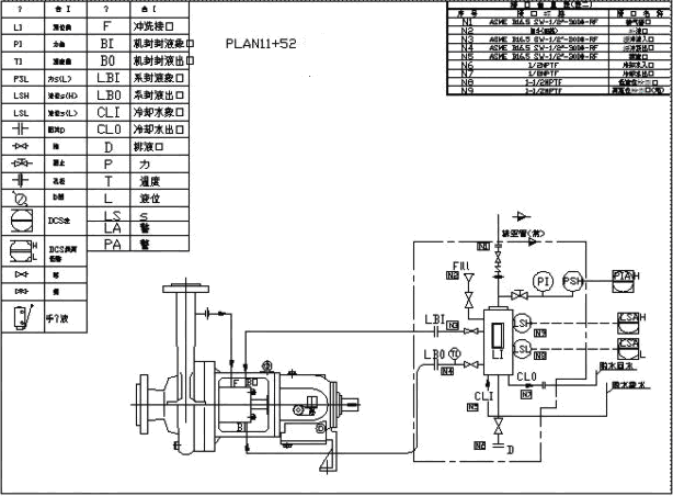
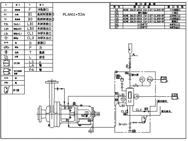
HR Series reservoir is according with API682, which can be used under pressured or non-pressured. External pressure or force source should be provided when pressured working. Fluid can be refilled under non-pressured condition or using booster to refill fluid. When mechanical seal shaft diameter is less than 60mm, choose HR5012 Series; when its shaft diameter is more than 60mm, choose HR5020 Series. Reservoir and connection is shown as Figure 1 and Figure 2.
Parameters:
| Type | Heat Exchange Area& (m2) | Operating Pressure (Mpa) | Operating Temperature (oC) | Total Area (L) |
| HR5012 | 0.3 | 0~5 | -200~120 | 16.6 |
| HR5020 | 0.4 | 0~5 | -200~120 | 27.8 |
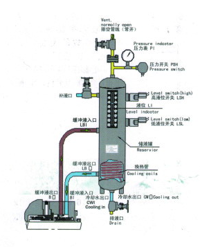
API 52 Plan A:
Mainly used for tandem mechanical seal non-pressured buffer fluid through reservoir, circulation power are provided by pumping ring in he cartridge mechanical seal. Mainly applied in the media i.e. easy vaporized gas, flash hydrocarbon, and dangerous, poisonous, harmful media. Pressure of buffer fluid in the reservoir is atmospheric pressure, if the seal in the media side leaks into atmosphere side directly, the pressure in the reservoir will become higher and fluid will be exhausted through draining pipe. Seal leakage will be monitored through level switch on the reservoir. Buffer fluid should be selected same as processing media. Pressure switch sets alarm of high pressure: commonly 0.1MPa.
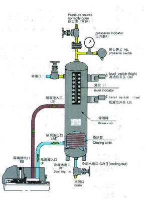
API 53 Plan A:
Mainly used for tandem or double mechanical seal pressured barrier fluid through reservoir, circulation power are provided by pumping ring in he cartridge mechanical seal. Mainly applied in the media i.e. easy vaporized gas, flash hydrocarbon, high temperature, dangerous, poisonous, harmful, easy crystallization and containing impurity etc. Pressure of barrier fluid in the reservoir must be more than media pressure (0.4-0.17Mpa). If the seal in the media side happens leaking, the barrier fluid in the reservoir will enter into sealed fluid to prevent sealed media leaking into the air. Seal leakage will be monitored through level switch on the reservoir. Barrier fluid should be selected same as processing medium. Pressure switch sets alarm of low pressure. Alarm value often use seal chamber`s pressure of pumping media 0.05Mpa.
2. HP Series Fluid Reservoir
Operating limits and descriptions HP Series reservoir is designed for supplying storage and keeping pressure for buffer fluid or barrier fluid in API Plan 52 and API Plan 53A, which is plain end and welded design according to ANSI standard VIII part.
Parameters:
| Type | Heat Exchange Area (m2) | Operating Pressure (Mpa) | Operating Temperature (oC) |
| HP-3 | 0.15 | 0~5 | -20~150 |
| HP-5 | 0.50 | 0~5 | -20~150 |
3. HT Series Fluid Reservoir
Operating limits and descriptions
HT Series reservoir is according with API610, which can be used under pressured or non-pressured. External pressure or force source should be provided when pressured working. Fluid can be refilled under non-pressured condition or using booster to refill fluid.
Features: 1. Oval end and welded design according to ANSI standard VIII part.
2. Used as independent fluid reservoir or complete system
3. Equipped with high strength view window checking of liquid level
Parameters:
| Type | Operating Pressure (Mpa) | Operating Temperature (oC) | Total Area (L) |
| HT-08 | 0~5 | -20~150 | 8 |
| HT-12 | 0~5 | -20~150 | 12 |
| HT-16 | 0~5 | -20~150 | 16 |
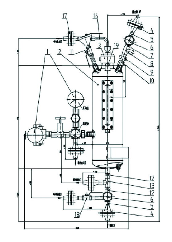
4. HG series Fluid Reservoir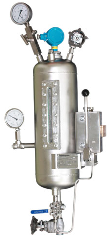
Designing Features:
● Standard design and accord with JB/T6630-1993, high pressure grade.
● All confined parts are welded with MIG processing technology and detection
checking, tested under 8MPa water pressure.
● Heat exchanging and cooling with coils.
● Liquid level display for cooling buffer fluid sets window made of quartz crystal of
temperature and pressure resistance Parameters
| Heat Exchange Area (m2) | Operating Pressure (Mpa) | Operating Temperature (oC) | Total Area (L) |
| 0.3 | 0~5 | -20~150 | 10 |
Typical system configuration
Type | Configuration |
| HG10 | fluid reservoir plus measuring unit plus coils and pipes of draining |
| HG11 | H10 plus hand refill pump |
| HG15 | H10 plus level switch |
| HG18 | H10 plus level switch plus hand refill pump |
| HG19 | H10 plus level switch plus pressure switch |
| HG20 | H10 plus pressure switch plus level switch plus hand refill pump |